
Dave's Archive > Kellogg Magneto Wall Switchboard
Back to dave's archive index, or see << previous - next >>
Kellogg Wall Magneto 20-line Switchboard
Circa 1930's, Kellogg Switchboard and Supply Co, Chicago.
See also: The Kellogg Page
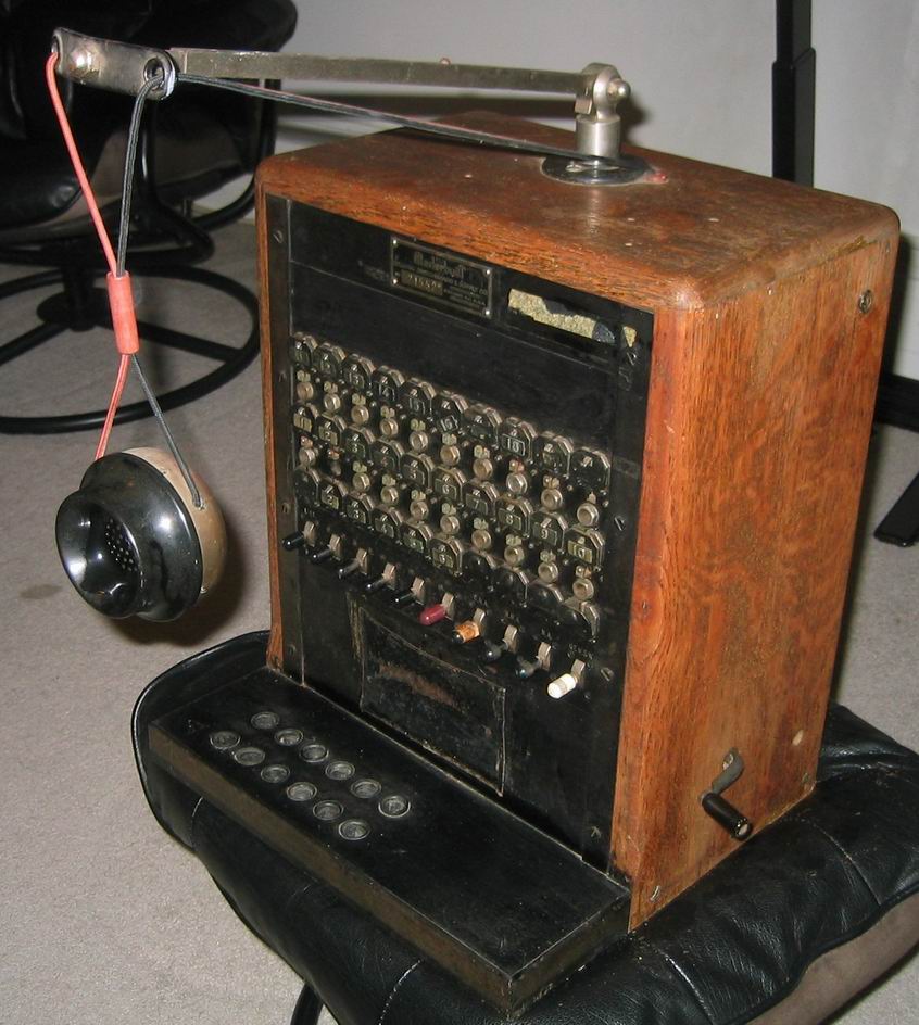
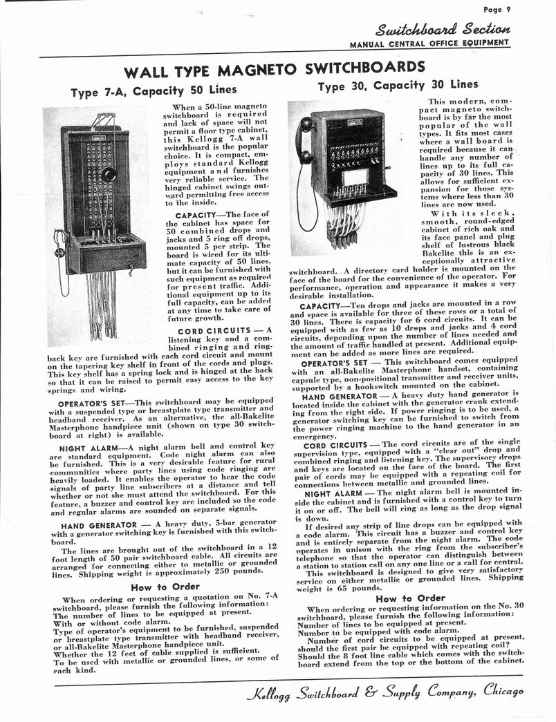
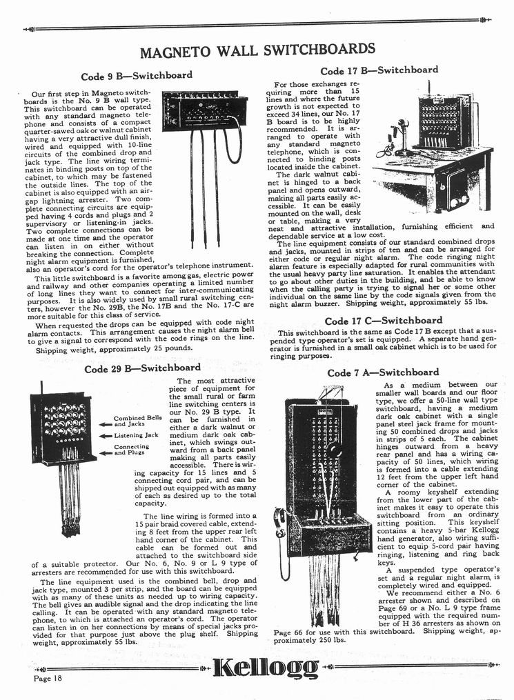
This is a 1930s-vintage Kellogg 'Masterbuilt' Wall-Type Magnetic Switchboard that probably served a small rural community with its 20 lines (although it could serve more than 20 households via party lines). Thanks to Roger Conklin, Odis Levrier and Steph Kerman for telling me everything I know about this. This switchboard has a hanging 'bulldog' transmitter (it may originally have had an older-style, 'solid-back' transmitter) and operators headset. The Kellogg catalog below shows a switchboard, the Type 30, very similar to mine except with a handset instead of the hanging transmitter and headset.
How the switchboard worked
(courtesy of Roger Conklin)
When a subscriber wanted to make a call he would first remove his receiver to make sure nobody else was already talking on his own party line. If the line was free he would replace the receiver and turn the crank on his phone to generate one long ring to call the operator. This would cause the drop shutter on his particular line to "drop" in the open position.
The operator would then insert a rear plug from any available cord circuit into the jack corresponding with and immediately below the drop that was down. Insetting the plug mechanically caused the drop to restore to its normal closed (vertical) position. Associated with each cord is a single switchboard key (toggle switch) The switchboard key, when pushed upward (or downward, I forget which), locks in the operated position. So when the operator inserted the answering plug and cord into the calling line, she would operate the key in the locked position. This connected her receiver and transmitter to the cord circuit so she would respond with "number please?" The calling subscriber would then give her the phone number he wanted to talk to.
The operator would then take the other cord of that same cord pair and plug it into the jack of the line the caller wanted. She would then operate this same key, but this time in the downward position, while simultaneously turning the crank on the generator. This applied ringing voltage to the called line. She would generate the particular combination of long and short rings to call the wanted subscriber. She would then restore the key to the locked listening position and wait until the called subscriber answered.
When the called subscriber answered, she would restore the listening key to the unlocked "normal" position thus disconnecting her talking circuit from the call. In the ringing position, the key was non-locking so when she took her finger off it returned to its normal position. She was then ready to handle subsequent calls using the other cord circuits.
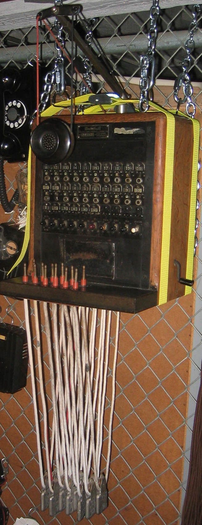
The combined drops and jacks terminate the lines. The cords come in "pairs"
and are for the purpose of connecting one line to another. The rear row of cords (with plugs on the ends) are referred to as answering cords, and the front row are completing cords. Each answering cord is electrically connected internally to its corresponding completing cord.
If the called subscriber had not answered on the first ring, she would repeat the ringing process, perhaps several times, until the subscriber answered or, if there was no answer, she would tell the caller "sorry, no answer" and then disconnect both cords.
The row of partially-equipped drops (with no associated jacks) at the bottom are supervisory (often called "ring-off") drops. When a call was completed, the calling subscriber, upon hanging up, was expected to turn his crank to generate one short ring. That caused the ring-off drop associated with that particular cord circuit to drop to the horizontal position to tell the operator that the call was done. She would normally open her listening key to make sure the call was over, and then disconnect it by removing both the calling and called cords. The ring-off drop was restored manually by the operator.
At the right side of the board there are some keys not associated with the cord circuits. One of them is probably a night alarm key. When that key was operated to its locked position, the night alarm was activated. When activated, a DC operated bell inside the switchboard, like a door bell, was connected so that whenever a drop was down, it would ring continuously until the operator restored the drop by inserting a calling plug, or restored it manually. It rang for both line and ring-off drops. This allowed the operator to sleep at night or temporarily step away from the switchboard during the day.
If a subscriber wanted to talk to someone on his own line, the operator's assistance was not required, nor was a cord circuit used. He would simply (1) make sure the line was free, (2) hang up and ring the code ring for the person on his own line and (3) take the receiver down and wait for the other party to answer. The operator would simply ignore and restore manually the drop on that line when the caller turned his crank to generate the ringing code for his neighbor. The armature vibrated in response to the code ring generated so that if there was anything other than one long ring, she ignored it. If she was away from the switchboard and the night alarm was on, she would return to the switchboard and plug in to answer; not knowing it was a call on the same line for another party. The subscriber would respond to the operator with "calling on my line" and she would then simply disconnect the plug.
Jacks = the two rows of ten jack, one per phone line
Drops = the numbered metal flaps above and below the jacks
Cords (not shown) = cords with plug end that operator used to connect the calls
Back to dave's archive index